

- Week 1
- Week 2
- Week 3
- Week 4
- Week 5
- Week 6
- Week 7
- Week 8
- Week 9
- Week 10
- Week 11
- Week 12
- Week 13
- Week 14
- Week 15
- Week 16
- Week 17
- Week 18
- Week 19
- Week 20
- Week 21
- Day 75
- Day 76
- Day 77
- Day 78
- Day 79
- Day 80
- Day 81
- Week 22
- Week 23
- Week 24
|
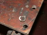
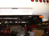
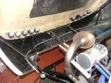
One of the things I remembered a couple of days ago was that I hadn't put in the lambda sensor hole. After checking with John, my ECU doesn't require two lambda sensors, so I was able to use the one from the downpipe I had cut up earlier. The first thing was to cut off the hole (I've been told it's an M18 thread size).
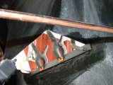
Using a hole cutter, I drilled an 18mm hole in the pipe, just after the header.
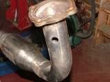
And then I welded the hole over it.
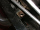
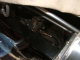
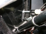
I then put it on the engine, and realised I'd made a mistake...
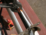
...the chassis is in the way. If I'd drilled it 20mm lower, or 10° over, it would've been fine. Since it didn't take that long to do, I had another go - after checking a few things out first. The tail pipes are fairly level - the left hand one is 2mm higher than the right.
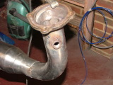
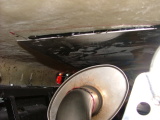
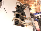
I took it off, modified the tail pipes, cut the hole off, welded a plate over the hole, and drilled a new one before welding the hole back on.
Much better. I also checked the clearance and position of the exhaust shield I'd made.
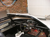
I got some new edging material yesterday, so I fitted it around the windscreen.
And also over the corners.
One of the bolts on the steering wheel mount was a tiny bit too short, so I replaced it with another one.
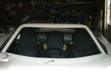
That's much better! Since it was a nice day, I opened the garage door - and took a picture of the three seats in place.
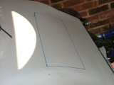
Scott's Aeon had an inspection hatch in the front, and other builders are doing the same (it's a very good idea). I decided to follow suit. First of all, I drew the outline of what I wanted.
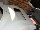
It's trapezoidal in shape, so knowing which way up it goes is easy. I then cut it out using an angle grinder.
I bonded some thick steel bar to the top of the inlet - this would allow me to make a nice rounded edge for the SVA, and also give it some strength.
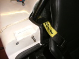
While that was going off, I replaced the gromit I'd attempted to make for the handbrake with some edging material which was able to take the shape better.
I then bonded some strips of GRP to the inside of the inspection hole so the panel won't fall through. I'll also put some rivnuts in the corners and some foam to make it more waterproof.
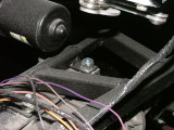
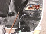
It was then time to start the wiring. Tomorrow's meant to be wet, so as I can only open the nose section when the door's open, I started with the front. I'm using 7-core cable (although only 6 of them are actually in use) to carry the main wire - it's similar to trailer cable, except higher current capacity.
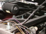
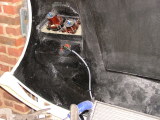
I've also fitted a plug so the nose section can come off without disturbing all the wiring. Unfortunately, my bag of 3mm spade connectors has gone AWOL, so I couldn't fit any of the indicators or sidelights. I've ordered another bag in case I can't find it (but I'm not sure if they'll arrive tomorrow or Monday). I then did something similar at the back. The nmbers above the light corresponds to the cable that it's connected to.
And as a final job, I ran a cable from the back to the front for the rear lights. Each cable is numbered - what I've done so far is:
The first three are actually the same funtion. |
Copyright © 2005-2007 Tribbeck.com / Jason Tribbeck